Earlier we had mentioned that the memory limits the speed of the CPU. Now there is one more case. In a pipelined design few instructions are in some stage of execution. There are possibilities for some kind of dependency amongst these set of instructions and thereby limiting the speed of the Pipeline. The dependencies occur for a few reasons which we will be discussing soon. The dependencies in the pipeline are called Hazards as these cause hazard to the execution. We use the word Dependencies and Hazard interchangeably as these are used so in Computer Architecture. Essentially an occurrence of a hazard prevents an instruction in the pipe from being executed in the designated clock cycle. We use the word clock cycle, because each of these instructions may be in different machine cycle of theirs.
There are three kinds of hazards:
- Structural Hazards
- Data Hazards
- Control Hazards
There are many specific solutions to dependencies. The simplest is introducing a bubble which stalls the pipeline and reduces the throughput. The bubble makes the next instruction wait until the earlier instruction is done with.
Structural Hazards
Structural hazards arise due to hardware resource conflict amongst the instructions in the pipeline. A resource here could be the Memory, a Register in GPR or ALU. This resource conflict is said to occur when more than one instruction in the pipe is requiring access to the same resource in the same clock cycle. This is a situation that the hardware cannot handle all possible combinations in an overlapped pipelined execution.
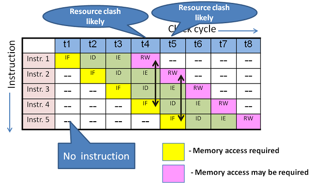
Observe the figure 16.1. In any system, instruction is fetched from memory in IF machine cycle. In our 4-stage pipeline Result Writing (RW) may access memory or one of the General Purpose Registers depending on the instruction. At t4, Instruction-1(I1) is at RW stage and Instruction-4(I4) at IF stage. Alas!. Both I1 and I4 are accessing the same resource i.e memory if I1 is a STORE instruction. How is it possible to access memory by 2 instructions from the same CPU in a timing state? Impossible. This is structural dependency. What is the solution?
Solution 1: Introduce bubble which stalls the pipeline as in figure 16.2. At t4, I4 is not allowed to proceed, rather delayed. It could have been allowed in t5, but again a clash with I2 RW. For the same reason, I4 is not allowed in t6 too. Finally, I4 could be allowed to proceed (stalled) in the pipe only at t7.
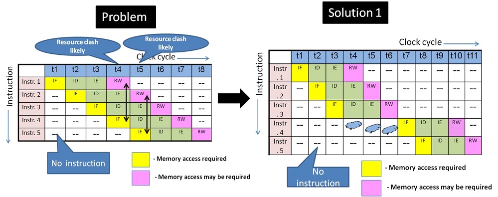
This delay is percolated to all the subsequent instructions too. Thus, while the ideal 4-stage system would have taken 8 timing states to execute 5 instructions, now due to structural dependency it has taken 11 timing states. Just not this. By now you would have guessed that this hazard is likely to happen at every 4th instruction. Not at all a good solution for a heavy load on CPU. Is there a better way? Yes!
A better solution would be to increase the structural resources in the system using one of the few choices below:
- The pipeline may be increased to 5 or more stages and suitably redefine the functionality of the stages and adjust the clock frequency. This eliminates the issue of the hazard at every 4th instruction in the 4-stage pipeline
- The memory may physically be separated as Instruction memory and Data Memory. A Better choice would be to design as Cache memory in CPU, rather than dealing with Main memory. IF uses Instruction memory and Result writing uses Data Memory. These become two separate resources avoiding dependency.
- It is possible to have Multiple levels of Cache in CPU too.
- There is a possibility of ALU in resource dependency. ALU may be required in IE machine cycle by an instruction while another instruction may require ALU in IF stage to calculate Effective Address based on addressing mode. The solution would be either stalling or have an exclusive ALU for address calculation.
- Register files are used in place of GPRs. Register files have multiport access with exclusive read and write ports. This enables simultaneous access on one write register and read register.
The last two methods are implemented in modern CPUs. Beyond these, if dependency arises, Stalling is the only option. Keep in mind that increasing resources involves increased cost. So the trade-off is a designer’s choice.
Data Hazards
Data hazards occur when an instruction's execution depends on the results of some previous instruction that is still being processed in the pipeline. Consider the example below.
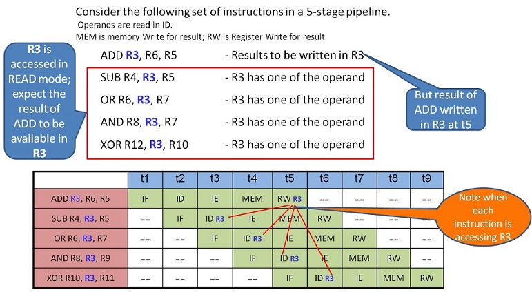
In the above case, ADD instruction writes the result into the register R3 in t5. If bubbles are not introduced to stall the next SUB instruction, all three instructions would be using the wrong data from R3, which is earlier to ADD result. The program goes wrong! The possible solutions before us are:
Solution 1: Introduce three bubbles at SUB instruction IF stage. This will facilitate SUB – ID to function at t6. Subsequently, all the following instructions are also delayed in the pipe.
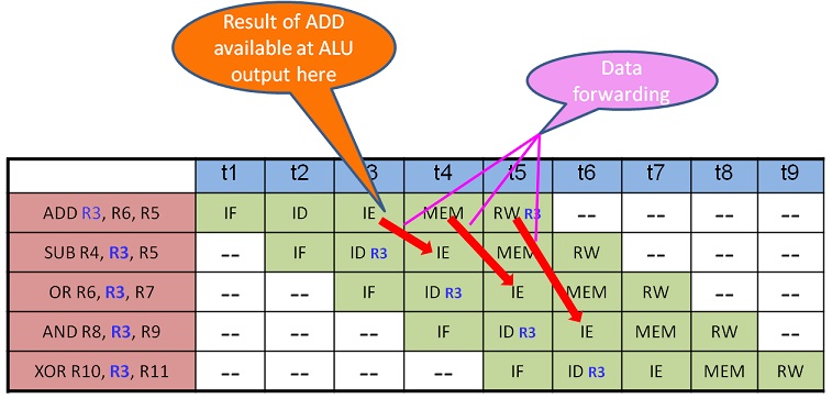
Solution 2: Data forwarding - Forwarding is passing the result directly to the functional unit that requires it: a result is forwarded from the output of one unit to the input of another. The purpose is to make available the solution early to the next instruction.
In this case, ADD result is available at the output of ALU in ADD –IE i.e t3 end. If this can be controlled and forwarded by the control unit to SUB-IE stage at t4, before writing on to output register R3, then the pipeline will go ahead without any stalling. This requires extra logic to identify this data hazard and act upon it. It is to be noted that although normally Operand Fetch happens in the ID stage, it is used only in IE stage. Hence forwarding is given to IE stage as input. Similar forwarding can be done with OR and AND instruction too.
Solution 3: Compiler can play a role in detecting the data dependency and reorder (resequence) the instructions suitably while generating executable code. This way the hardware can be eased.
Solution 4: In the event, the above reordering is infeasible, the compiler may detect and introduce NOP ( no operation) instruction(s). NOP is a dummy instruction equivalent bubble, introduced by the software.
The compiler looks into data dependencies in code optimisation stage of the compilation process.
Data Hazards classification
Data hazards are classified into three categories based on the order of READ or WRITE operation on the register and as follows:
- RAW (Read after Write) [Flow/True data dependency]
This is a case where an instruction uses data produced by a previous one. Example
						ADD R0, R1, R2
						SUB R4, R3, R0
- WAR (Write after Read) [Anti-Data dependency]
This is a case where the second instruction writes onto register before the first instruction reads. This is rare in a simple pipeline structure. However, in some machines with complex and special instructions case, WAR can happen.
						ADD R2, R1, R0
						SUB R0, R3, R4
- WAW (Write after Write) [Output data dependency]
This is a case where two parallel instructions write the same register and must do it in the order in which they were issued.
						ADD R0, R1, R2
						SUB R0, R4, R5
WAW and WAR hazards can only occur when instructions are executed in parallel or out of order. These occur because the same register numbers have been allotted by the compiler although avoidable. This situation is fixed by renaming one of the registers by the compiler or by delaying the updating of a register until the appropriate value has been produced. Modern CPUs not only have incorporated Parallel execution with multiple ALUs but also Out of order issue and execution of instructions along with many stages of pipelines.
Control Hazards
Control hazards are called Branch hazards and caused by Branch Instructions. Branch instructions control the flow of program/ instructions execution. Recall that we use conditional statements in the higher-level language either for iterative loops or with conditions checking (correlate with for, while, if, case statements). These are transformed into one of the variants of BRANCH instructions. It is necessary to know the value of the condition being checked to get the program flow. Life is complicating you! So it is for the CPU!
Thus a Conditional hazard occurs when the decision to execute an instruction is based on the result of another instruction like a conditional branch, which checks the condition’s resultant value.
The branch and jump instructions decide the program flow by loading the appropriate location in the Program Counter(PC). The PC has the value of the next instruction to be fetched and executed by CPU. Consider the following sequence of instructions.
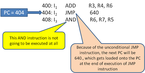
In this case, there is no point in fetching the I3. What happens to the pipeline? While in I2, the I3 fetch needs to be stopped. This can be known only after I2 is decoded as JMP and not until then. So the pipeline cannot proceed at its speed and hence this is a Control Dependency (hazard). In case I3 is fetched in the meantime, it is not only a redundant work but possibly some data in registers might have got altered and needs to be undone.
Similar scenarios arise with conditional JMP or BRANCH.
Solutions for Conditional Hazards
- Stall the Pipeline as soon as decoding any kind of branch instructions. Just not allow anymore IF. As always, stalling reduces throughput. The statistics say that in a program, at least 30% of the instructions are BRANCH. Essentially the pipeline operates at 50% capacity with Stalling.
- Prediction – Imagine a for or while loop getting executed for 100 times. We know for sure 100 times the program flows without the branch condition being met. Only in the 101st time, the program comes out of the loop. So, it is wiser to allow the pipeline to proceed and undo/flush when the branch condition is met. This does not affect the throttle of the pipeline as much stalling.
- Dynamic Branch Prediction - A history record is maintained with the help of Branch Table Buffer (BTB). The BTB is a kind of cache, which has a set of entries, with the PC address of the Branch Instruction and the corresponding effective branch address. This is maintained for every branch instruction encountered. SO whenever a conditional branch instruction is encountered, a lookup for the matching branch instruction address from the BTB is done. If hit, then the corresponding target branch address is used for fetching the next instruction. This is called dynamic branch prediction.

Figure 16.6 Branch Table Buffer This method is successful to the extent of the temporal locality of reference in the programs. When the prediction fails flushing needs to take place.
- Reordering instructions - Delayed branch i.e. reordering the instructions to position the branch instruction later in the order, such that safe and useful instructions which are not affected by the result of a branch are brought-in earlier in the sequence thus delaying the branch instruction fetch. If no such instructions are available then NOP is introduced. This delayed branch is applied with the help of Compiler.
I do not want to load the reader with more timing state diagram. But I am sure the earlier discussions would have familiarised the reader to understand with words.
Last but not the least, in a pipelined design, the Control unit is expected to handle the following scenarios:
- No Dependence
- Dependence requiring Stall
- Dependence solution by Forwarding
- Dependence with access in order
- Out of Order Execution
- Branch Prediction Table and more
Pipeline Hazards knowledge is important for designers and Compiler writers.
Modern Processors implement Super Scalar Architecture to achieve more than one instruction per clock cycle. This architecture has more execution pipes like one independent unit each for LOAD, STORE, ARITHMETIC, BRANCH categories of instructions.

