A program is written and submitted for execution to the computer. Mostly, the programmer or a student wishing to execute a program works in the IDE (Integrated Development Environment) of the Language Compiler. The sequence of steps is the program is compiled, linked, loaded and executed. The Linker output is machine code. The loader loads the program machine code in Main Memory from a particular address. The CPU executes the machine code from the starting address in a sequential manner following the flow of the code. To put it harshly, CPU just obeys the sequence of instructions that makes up the code for the program; it does not understand the program as a whole. In fact, for this reason, computers are said to "Garbage In Garbage Out".
Machine Language
Machine language is the native language of the CPU that it understands. In the hierarchy of computer languages, machine language is at the lowest level and closest to the hardware as represented in figure 4.1. Machine language is unique to each CPU and partly generic to the family of the CPU (Ex. Intel series). A program converted into an executable file (.exe) on a CPU is not executable in another brand of CPU. For example, an executable file generated in Intel CPU will not run on another CPU like AMD or so. The program will have to be recompiled on the other system and the executable code to be regenerated.

Machine language is in binary form. This is nothing but the CPU instructions in the instruction format of the CPU as defined by the Instruction Set Architecture (ISA).
Instructions
An instruction details the CPU of "What to Execute?", "Where to Execute?" and "How to Execute?". For example, a code written by the programmer as TOTAL = TOTAL + SUBTOTAL is converted as an instruction(s) that tells the CPU to add the contents of the two memory locations where the variables TOTAL and SUBTOTAL are stored and put the result in location TOTAL.
Every CPU has an Instruction Set and format for the instructions. Essentially an instruction consists of minimum two components i.e the instruction code (opcode) and the operand for the instruction as in figure 4.2.

Opcode: Specifies the type of operation to be performed.
Operand: Provides information on the data needed for the instruction execution.
For a computer to be usable to the user, we can imagine that at the minimum that the system should be communicable to the user using the I/O devices and also do some arithmetic and logical operations as demanded by the user. Additionally, the system needs a few data movement instructions to meet these expectations. Thus it is clear that an Instruction set is associated with each CPU. Modern CPU’s have a variety of instructions that are more than the minimum to meet the demands of the world with efficiency. Along with each instruction, how and where of data is provided, thus encoding the instruction format. This is in Binary form occupying a particular length of the word(s).
Instruction Set Classification
The instruction set of any processor broadly fits into the categories as in figure 4.3 along with examples. The first five categories are mandatory while the next four are generally available in advanced or new generation processors. The Instruction set is part of the Instruction Set Architecture( ISA). Therefore the Data path, the Registers, Memory Interface and the Instruction set, altogether ensure the design of the CPU and its best utilization. The number of instructions for a processor may range from less than 100 to few hundreds plus. It is noteworthy, that a large number of instructions does not imply that the processor is powerful. More often, to provide downward compatibility within the processor family variants of each instruction adds up to the list, making the set larger. I am sure you are aware that programs created in 8086 CPU get executed in today’s Intel Processors.
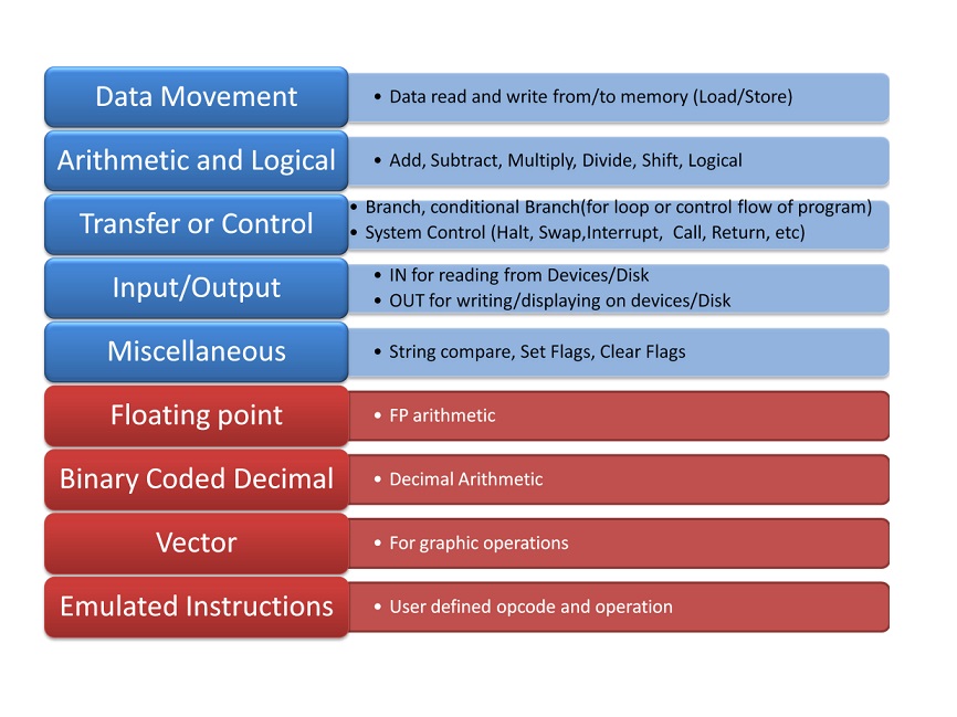
Let us see the purpose of each class of instructions. For easy understanding, the examples are written in the mnemonic code. R refers to register in CPU, any name refers to the variable. First part is the instruction mnemonic. The example instructions do not pertain to any particular CPU.
Data Movement Instructions: These support movement of data between registers, registers to memory, memory to register. Few CPU support memory to memory movement of data too. Data movement instructions are named as either “Move” or Load/Store” instructions. This category is most frequently used by CPU while executing program code. For example:
			Move 	R1,	Total
			Move 	Total,	R1
			Load 	R1, 	Total
			Store 	R1, 	Total
Arithmetic and Logical Instructions: This category of instructions carry out calculations. The minimum in this category is ADD, SUB, AND, OR, XOR, SHIFT. Multiply and Divide can always be emulated using successive addition or subtraction. This was the case in very early systems. However, MULTIPLY and DIV are part of the instruction set as hardware execution is more efficient than emulation. Few CPUs have CMP (Compare) instruction.
The logical instructions are required to implement the condition checking of "For Loops, While Loops, IF, etc.,".
At the end of execution of arithmetic and logical instructions, depending on the result in Accumulator, Condition Codes (Zero, Sign, Overflow, Carry – ZSOC) are set, implying the outcome of the instruction execution. Generally, these flags are useful in controlling the flow of the program. For example:
			ADD	R1,	TOTAL
			ADD	R1,	R2, R3
			XOR	R4,	TOTAL
			MUL	R4,	MARKS
Transfer or Control Instructions: This category of instructions facilitate change in program flow described by the control structures in the high-level language. BRANCH or JMP instructions along with Condition Code flags achieve the requirement. Subroutine CALLS, RETURNS are categorized here. For example:
			JMP	LABLE1	Jump
			JNZ	LABLE1	Jump on Not Zero
			BZ	LABLE2	Branch on Zero
			BNE	LABLE3	Branch on Not Equal
Input/Output Instructions: There are two ways of doing Input/Output operations. Intel family uses In and Out Instructions on the I/O registers for communication or data transfer with I/O devices. These I/O registers are numbered as Ports. Motorola family uses Data movement instructions assigning memory addresses to I/O registers. The former is called I/O mapped I/O whereas the later is called Memory-mapped I/O. For example:
			IN	Port#232
			OUT	Port#234
			Move	R1, #FFEEEE
Miscellaneous Instructions: NOP (No Operation) is a famous dummy instruction but a very useful one in this category. Some of the CPUs allow user-defined interrupt. These interrupts can be activated using Instructions. HALT is another very important instruction which brings the system to halt when "Shutdown". System Control is either grouped here or as Control Instructions. For example:
			HALT
			NOP
			INT
Floating Point Instructions: We had seen in the previous chapter that specialised hardware is required for efficient Floating-point operations. This hardware works independently of the CPU. Floating-Point Arithmetic instructions with unique opcode are helpful.
			FLD	FP Load
			FST	FP Store
			FADD	FP ADD
			FSUB	FP Subtract
			FMUL	FP Multiply
Binary Coded Decimal Instructions: Decimal Number system hardware speeds up decimal calculations. In the absence of this hardware, every time conversion to binary and reverse conversion to decimal is required. Similar to floating arithmetic instructions specialized decimal hardware is available.
Vector Instructions: This group is specific to display. Graphic operations like zoom, resize, flip etc require heavy calculations on Vector basis. Matrices operations utilize vector instructions.
Emulated Instructions: User-defined opcode and operation fall into this category. Very few CPU support this type.
CPU architecture design radically differs based on the size of the Instruction set. Accordingly, there are two categories namely Reduced Instruction Set Computer (RISC) and Complex Instruction Set Computer (CISC). As the name implies, RISC has fewer instructions in the set and CISC has a large number of instructions. No matter, both are equally functionally complete. MIPS, ALPHA, PA-RISC, Intel i860, Motorola 88000, ARM are all examples of RISC CPU. Intel X86 series, Motorola 68K series, VAX are all examples of CISC CPU. Frequently we will be referring to RISC and CISC. The trade-off is between the size of the program code and the simplicity in decoding the instructions by the hardware.
Instruction Formats and Classification
A variety of instructions have to be encoded along with operand information. Each instruction has Opcode and zero, one or more Operands and /or the address of those operands. There are many ways of conveying the operand address. Try to recollect, in how many ways do you reference a variable in your program, from simple assignment to pointers, stack, etc. All these definitions in a program necessarily have to be encoded in a set of machine-level instructions. Not an easy task!
The components to be considered while deciding and designing instruction format is:
- The number of instructions in the instruction set
- The number of CPU registers to be addressed
- Size of Main memory to be addressed and organization
- Addressing modes to be mapped
Encoding of Instructions is called Instruction Format. There are two generic ways to encode instructions.
- Fixed length Instruction Format - RISC uses fixed-length encoding.
- Variable Length Instruction Format - CISC uses variable-length encoding.
Variable Length Instruction format
- Each instruction occupies only the space required by it to convey the operands. No redundant use of memory space.
- Essentially this format provides more options to address more operands.
- Calculating the next instruction location is complex and depends on the current instruction type.
- The fetch and decode logic and Control Unit design is complex.
- Code efficiency is possible, but frequent memory reference implies relatively reduced efficiency.
- A Large number of instructions have different opcodes but same function, implying varying addressing modes.
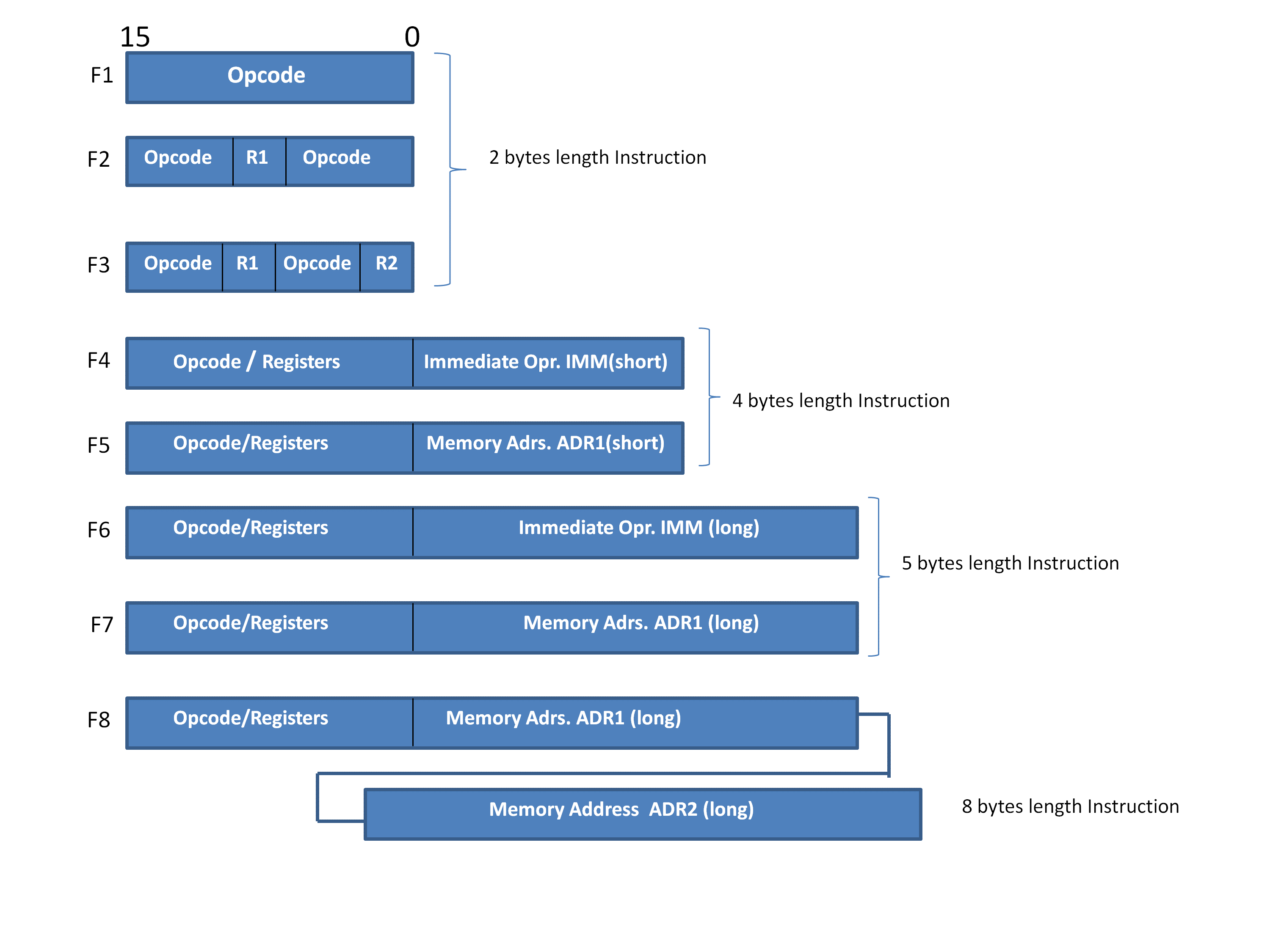
Fig. 4.4 is the instruction set format of Motorola M6800 CISC CPU. This is a supportive figure to understand the characteristics of a variable-length format. As you see, there 8 ways in which the instruction is encoded varying from 2 bytes length to 8 bytes length. It is observed that the length differs depending upon the way the operand address is conveyed.
Fixed Length Instruction format
- Each Instruction occupies the same amount of space. The length of the instruction is fixed irrespective of the opcode.
- The instruction fetch process is simpler. The next instruction address is obtained by incrementing the Program Counter by a fixed count.
- The instruction decoding process is also simpler and hence the Control Unit design is less complex comparing variable-length format.
- Faster and better performance, as the design, makes use of CPU Registers more effectively.
- The program code (machine code) for these machines is longer and proportional to the number of instructions.
- Few simple instructions equivalent to HALT, NOP which do not require any operand also occupies the same length and size of memory. A little waste of memory space at the cost of CPU efficiency.
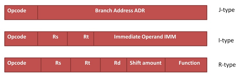
MIPS Rxxxx series is a RISC processor. It simply has 3 variants of formats but all have the same word length. Also, it is observed that registers are used than the memory in referencing operands.
