Instruction set architecture (ISA) describes the processor (CPU) in terms of what the assembly language programmer sees, i.e. (a) the instruction set and instruction format, (b) Memory Model and addressing methods and (c) the programmer accessible Registers. These three details of the computer are also called Programmer's Model of a Computer. The architecture design goes along with all the above.
Features of Instruction Set are:
- Instruction Length (Number of Bits or word size)
- Number of Instructions in the Instruction Set
- CPU Internal Storage ( Registers or Stack and size)
- Operand Location (Register, Memory, Immediate..)
- Number of Operands that can be accommodated in the Instruction
- Size of Operands
- Instruction format choice (Variable or Fixed)
Internal Storage of CPU
Although CPU brings instructions from Main Memory and executes, some kind of Internal storage is required to carry out the instruction execution. This Internal Storage has a place in Instruction format; it is also accessible to Assembly language programmers. There may also be additional storage in the CPU which are not accessible at the Instruction level.
- Stack Architecture
- Accumulator Architecture
- General Purpose Register Architecture –
- Register- Memory Machines – CISC
- Register-Register Machines - RISC
Stack Architecture
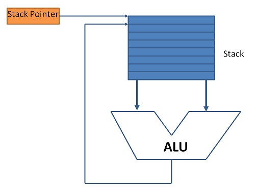
CPU Internal Storage is organized as Stack Memory and is used in the execution of instructions. A stack resembles the array of contiguous storage locations stacked one over the other in the order of their address. All read /write operations refer to the top of the stack (TOS). TOS is the only accessible location in the stack. PUSH operation writes a word into the next location TOS+1 and causes this location to become new TOS .i.e. a PUSH operation causes a stack to grow; Similarly a POP operation reads the word form the top of the stack and updates TOS with (TOS-1) thus diminishing the stack size. Figure 5.1 diagrammatically explains the Stack CPU operation.

The addition operation C=A+B in a stack machine has the following set of instructions:
			PUSH A
			PUSH B
			ADD
			POP C
ADD instruction causes the top two words of the stack to be added in ALU; PUSH loads the data into stack and POP causes the TOS to be read. A key component of stack CPU is Stack Pointer SP register, which stores the internal address of TOS and automatically adjusts the TOS for every PUSH and POP operation. A Program counter keeps track of instruction addresses in the usual manner as the operands are taken from the stack.
A stack CPU evaluates arithmetic and other instructions using Polish notation, wherein X+Y is written as x y +. The expressions are evaluated from left to right. The advantage of Polish notation is that it eliminates the need for parenthesis.
In a stack machine, both instructions and operands implicitly taken from the stack. There is no explicit memory access for operand fetch. No operand is part of the instruction. For this reason, the stack architecture machines are called "Zero Address Machines" and the instruction set for these machines are called Zero address instructions.
Olden day's Burroughs B5000 and HP systems are examples of this unique stack architecture. The recent such computer is SUN PicoJava microprocessor designed for fast execution of compiled Java code. Stack concept is widely used in pocket calculators.
The advantage of Zero address machines is good code density and being a simple model to evaluate expressions. However, there are issues like difficulty in generating efficient code.
Accumulator Architecture
In accumulator architecture, one operand is implicitly in the accumulator. The other operand is explicitly given as memory location. For this reason, these CPUs are said to be "1-Address Machines" and the instruction set is said to be 1_address Instruction i.e. along with instruction only one operand can be passed on. This architecture strictly follows Von Neumann architecture’s Stored Program Concept.
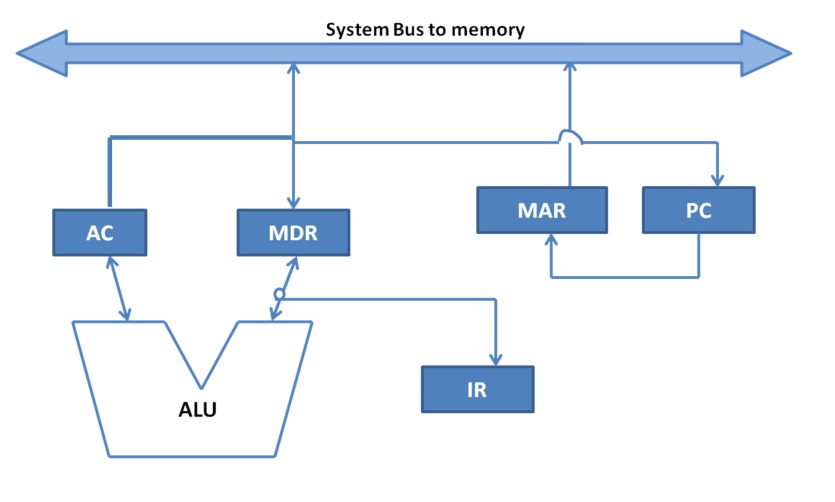
Accumulator based CPU comprises a small set of registers namely Memory Address Register (MAR), Memory Data Register (MDR), Instruction Register (IR) and Program Counter (PC). The data path of the Accumulator based CPU is shown in figure 5.2. There is a system bus connecting the main memory and the registers. This also shows the connectivity of the said registers. The Accumulator (AC) plays a central role in the execution of instructions.

The same example C=A+B is executed as
			LOAD A
			ADD B
			STORE C
In the above example, note that each instruction has one operand only. The merit of accumulator architecture is the reduced internal complexity of the CPU but memory traffic is large.
General Purpose Register Architecture
The CPU has a set of General Purpose registers (GPRs) as internal storage, in addition to those registers mentioned in the Accumulator architecture. The GPRs are accessible to assembly language programmers. Registers are not only structurally closer to CPU but also have much less access time than main memory. Operands and intermediate results are stored in these registers, thereby restricting the memory access during program execution. This, in turn, increases the performance of the CPU. Both CISC and RISC follow this architecture. Nowadays CPUs configuration includes a large number of GPRS in the range of 32 to 100+.

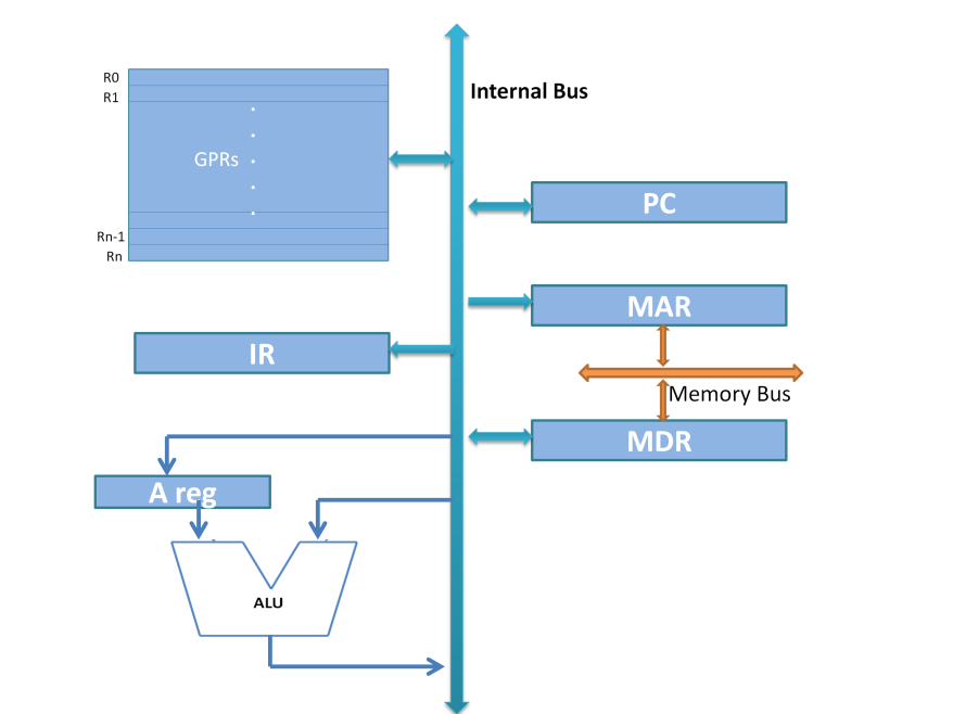
GPR architecture design comes with one, two or more internal bus in the CPU data path facilitating the effective use of the registers for operand read/write. A single bus GPR architecture is shown in figure 5.3. It can be extrapolated to two or three buses to reduce the instruction execution cycle. In this, the instruction length is generally long so that max two operands are provided along with instruction. CISC has provision to describe two operand addresses in the instruction while RISC has provision for three operands or operand locations. RISC uses the GPRs more effectively than CISC for this purpose. For this reason, this architecture is called "Two Address machine" in the case of CISC implementation and "Three Address machine" in the case of RISC implementation.
In the cases, where the instruction requires more than one operand, Operand handling in GPR architecture is classified into three types:
- Register-Memory Type: One operand is referred to in memory and the other in GPR.
- Register-Register Type: Both operands or maximum of three operands are referred to in the register. The operands are preloaded into Registers form memory. This type is also known as "Load/Store architecture" practised in RISC.
- Memory to Memory Type: Both the operands are referred to in memory. An example of this case could be, string manipulation instructions where large strings are moved from one variable to the other.
The merits of GPR architecture are faster instruction completion. This architecture is suitable for code optimization by Compilers. The compilers use free registers to assign for the operand. Although longer instruction length was considered as a demerit, with technological advancement, it is no more a disadvantage.
From table 5.1 one can understand the effectiveness of the GPR architecture in creating effective equivalent code for an arithmetic equation.
Comparison of the three architectures
Two examples are dealt with to bring out clarity on how the number of machine instructions is reduced effectively in solving an equation. Not only the instruction, GPR architecture facilitates data path with more number of internal bus, which in turn reduces the time required to execute each instruction.
| Zero Address machine | One Address Machine | GPR Architecture | |
|---|---|---|---|
| Two address Machine | Three Address Machine | ||
| Instruction format includes Zero Operand | Instruction format includes One Operand | Instruction format includes Two Operands | Instruction format includes Three Operands |
| Opcode Only | Opcode + 1 Operand address | Opcode + 2 Operand addresses | Opcode + 3 Operand addresses |
| -- | Usually, the Operand address is a Memory address | Usually, both operands are referred to registers or one in a register and the other in memory | All the operands are preloaded into GPR Registers. |
| Ex 1: C=A+B, typical instructions required to execute this equation | |||
|
|
|
| Ex 2: T = (P x Q) + (R x S) , typical instructions required to execute this equation |
|
|
|
|
We deal with more details in the data path chapter. The last part of ISA, memory models and addressing is handled in the next chapter.

