Memory model and memory addressing is the third part of Instruction Set Architecture (ISA). Memory model for an ISA specifies the CPU addressable range of the memory, memory width and Byte organization. In the Stored Program Concept, Memory is the place where the program and data are loaded for execution. Thus the CPU needs to have a way to access the memory, i.e. obtain the address as part of instruction execution. Addressing modes of an ISA specifies how to calculate the Effective Address of the operand(s) from the instruction. Addressing mode is encoded in the instruction. Essentially the ISA addressing modes are largely a mapping to the variable referencing methods of the programming languages.
Addressing Modes
The outcome of Addressing mode is the Effective Address(EA). Effective Address is the address of the operand which is obtained by applicable calculations of the addressing mode specified in the instruction. Effective address reveals the location of the operand. The instruction format has provision to specify the information regarding operand location but probably in an encoded manner. It is a known fact that an operand may be in a GPR register, memory or in the instruction itself. The addressing modes encoding depends on (a)the range of addressing modes and (b) the degree of independence between opcodes and modes.
For convenience, we divide the instruction format into two parts, i.e. Part A containing Opcode, Addressing mode and Part B consisting of Displacement. The same instruction format is viewed in an encoded manner as in figure 6.1 for effective address calculation. We are aware that in an instruction format few bits are allotted for specifying the opcode. Similarly, there are few more bits allotted to specify the addressing mode. The balance number of bits in the instruction is called displacement. The number of bits allotted for these purposes and their position is part of the instruction format ISA. Generally, displacement is the last part of the instruction format while the other two occupy the initial part. There is no hard and fast rule that the opcode and addressing mode specifier have to be explicitly allotted bits and bit positions in the instruction. In some cases, the opcode itself implies the addressing mode. For example, there are instructions like ADDI (Add immediate) and ADD. These are issues specific to ISA implementation.

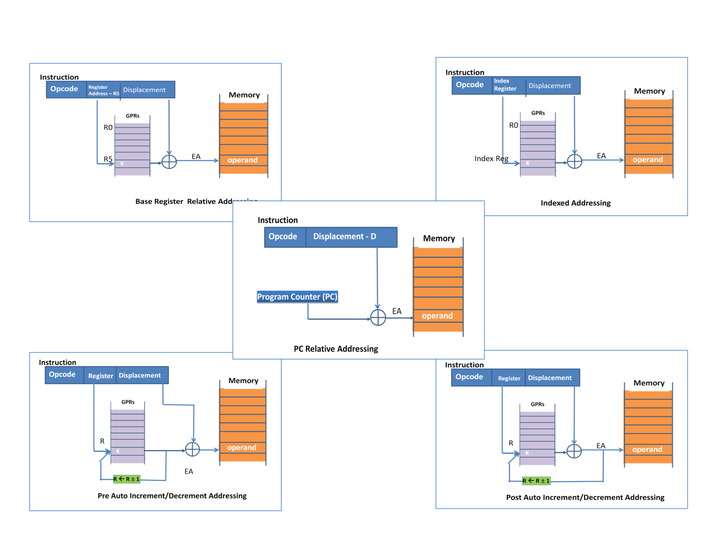
Most popular addressing modes supported by ISA are detailed in table 6.1 along with EA calculation and the purpose. Most popular are Immediate addressing mode and Direct Addressing modes. However, the names may differ among architectures. Figure 6.2a and 6.2b pictorially represent the interpretation of popular 10 addressing modes. Read table 6.1 along with figure 6.2a and 6.2b for enhanced understanding and interpretation.
| Addressing modes | Example Instruction | Operation of the Instruction | EA calculation | When used |
|---|---|---|---|---|
| Immediate Addressing | Load R5, #A | R5 <- A | Operand value is A and is given in the displacement field of the instruction. | A is declared as a constant in the program. |
| Memory Direct Addressing | Sub R1, A | R1 <- R1 – [A] | EA=A; A is given in displacement field and is the memory address of the operand | A is declared as a static variable in the program |
| Register Direct Addressing | Add R5, R7 | R5 <- R5+R7 | Operand value is in a register; loaded before ADD instruction | Declared as a variable in Program. |
| Memory Indirect Addressing | Load R5, (D) | R5 <- (M(D)) | EA= M(D); Value D in displacement field; Memory loc D contains value K, which is the address of the Operand | Use of Pointers. D has the pointer value to the operand. |
| Register Indirect Addressing | Add R5, (R6) | R5 <- R5+(M(R6)) | EA= M(R6); Operand is fetched from memory location pointed by Reg 6 content. | Use of Pointers. R6 is used to hold the pointer value instead of a memory location in the earlier case. This helps in faster execution. |
| PC Relative Addressing | JMP +D | PC <- PC+D | EA=PC+D; Generally associated with JMP kind of instructions. The program jumps to a location by D (Displacement Value) from the current PC. This becomes the next instruction. | Program control instruction managed by compiler mapped to program branch. An example could be CASE statements |
| Base Register Relative Addressing | Add R4, D | R4 <- R4+M(R5+D) | EA= R5+D; R5 here is used as the base register. D is the displacement value in the instruction. | Starting memory address of Data area is loaded in the Base register. Each variable is referenced from there. The Compiler takes care of this referencing. |
| Indexed Addressing | Add R5, D | R5 <- R5+ M(RI+D) | EA=RI+D; RI is notified as index register and holds the index value; D is the base memory location. The operand is at the location D+Index | Useful with Arrays. D is the array beginning. Index is the pointer to the element within the array. Useful in "for loops" for the count value. Indexing is in the control of the programmer. |
| Post Auto Increment/Decrement Addressing | Add R5, (R4)+ | a) R5 <- R5+M(R4); b)R4 <- R4±1 | EA=R4; A register, in this case, R4 is used for auto increment or decrement at the end of EA calculation. | Useful for stepping thru string processing like COPY or COMPARE in a large chunk |
| Pre Auto Increment/Decrement Addressing | a)R4 <- R4±1; b)R5 <- R5+M(R4); | Same as above. But the register update happens before EA calculation. |
The addressing modes are not limited to the above, there could be more as per the architecture demands. Further, the mnemonic representations, the step size, the definition of registers differ from CPU to CPU. Interested readers may take it as an exercise to go through the instruction set of different processors like Intel, AMD, Motorola, Power series etc.


Memory Model
Memory model defines both the internal storage GPRs and the Main Memory accessible to Assembly language programmer. Memory model also defines the byte alignment mode. A typical memory model is defined as:
- 64 GPRs of 32-bit width addressed as R0 to R63
- 16 GPRs as floating-point Registers addressed as R64 to R79
- 8 GPRs for vector operation addressed as R80 to R87
- Addressable main memory 1GB addressed as 0 to 1GB
- Byte alignment is Little Endian
For the logic designer, this specs mandates the internal bus and system bus requirements.
Byte Alignment
We know a byte is 8 bits. Larger word size can accommodate more information for both instruction and data in one memory operation. Essentially, this means a large bandwidth. Larger word size is achieved by assembling bytes. The assembly order and addressing the assembly is called Byte Alignment. There are two alignment methods namely Big Endian and Little Endian as represented in figure 6.3 and 6.4 respectively. Endian denoting the end position. Little Endian got its name as the LSB is byte 0. In Big Endian, byte 0 is MSB.
When operating within a machine, the byte order is often unnoticeable. However, the byte order is a problem when exchanging data among machines with a different ordering. Little Endian is followed by Intel, DEC, etc., while Big Endian is followed by IBM, Motorola.


Whenever more than a byte is to be accessed, generally a word is brought from memory and the desired part is taken by CPU. However, halfwords, words, doublewords all align to byte 0 address. Misalignment of addresses is a serious issue due to hardware logic implementation. Misalignment can still be handled with extra operations.

