Multiplication and Division are two other arithmetic operations frequently required even in simple mathematics. CPUs have set of instructions for integer MULTIPLY and DIVIDE operations. Internally these instructions are implemented as suitable algorithms in hardware. Not only integer arithmetic but also Floating-Point and Decimal instruction sets are also likely to have these MULTIPLY and DIVIDE sets of instructions in sophisticated CPUs. Hardware implementation increases the efficiency of CPU.
This chapter is important for those who want to understand the hardware implementation of Multiplication and Division.
Multiplication
Just recall with micro details as to how do we do multiplication using pen and paper. Then it is easier to visualize that it is possible to implement a hardware algorithm.
			Multiplicand M	= 12	   1100
			Multiplier Q	= 11	  x1011
						--------
						   1100
						  1100
						 0000
						1100
						--------
			Product P	= 132	10000100
As you see, we start with LSB of the Multiplier Q, multiply the Multiplicand, the partial product is jotted down. Then we used the next higher digit of Q to multiply the multiplicand. This time while jotting the partial product, we shift the jotting to the left corresponding to the Q–digit position. This is repeated until all the digits of Q are used up and then we sum the partial products. By multiplying 12x11, we got 132. You may realize that we used binary values and the product also in binary. Binary multiplication was much simpler than decimal multiplication. Essentially this is done by a sequence of shifting and addition of multiplicand when the multiplier consists only of 1's and 0's. This is true and the same, in the case of Binary multiplication. Binary multiplication is simple because the multiplier would be either a 0 or 1 and hence the step would be equivalent to adding the multiplicand in proper shifted position or adding 0's.
It is to be observed that when we multiplied two 4-bit binary numbers, the product obtained is 8-bits. Hence the product register (P) is double the size of the M and Q register. The sign of the product is determined from the signs of multiplicand and multiplier. If they are alike, the sign of the product is positive. If they are unlike, the sign of the product is negative.
Unsigned Multiplication
When multiplication is implemented in a digital computer, it is convenient to change the process slightly. It is required to provide an adder for the summation of only two binary numbers and successively accumulate the partial products in a register. The registers, Shift Counter and the ALU width is decided by the word size of the CPU. For simplicity of understanding, we will take 4-bit word length i.e the Multiplier (Q) and Multiplicand (M) are both 4-bits sized. The logic is extrapolated to the word size requirement.
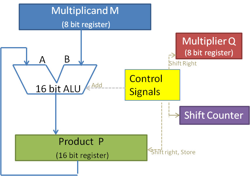
We need registers to store the Multiplicand (M) and Multiplier (Q) and each 4-bits. However, we use 8-bit register which is standard and minimum and hence the register to collect Product (P) is 16-bits. Refer to figure 9.1. The Shift counter keeps track of the number of times the addition is to be done, which is equal to the number of bits in Q. The shifting of the contents of the registers is taken care of by shift register logic. The ALU takes care of addition and hence partial product and product are obtained here and stored in P register. The control unit controls the cycles for micro-steps. The product register holds the partial results. The final result is also available in P when the shift counter reaches the threshold value.

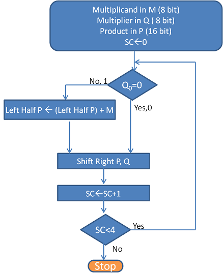
The flowchart for the unsigned multiplication is shown in figure 9.2 and table 9.1 explains the work out with an example of 12 x 11 values. The flowchart is self-explanatory of the unsigned multiplication algorithm. In an unsigned multiplication, the carry bit is used as an extension of the P register. Since the Q value is a 4-bit number, the algorithm stops when the shift counter reaches the value of 4. At this point, P holds the result of the multiplication.

| Operation Step | Shift Counter Value | Multiplicand M | Multiplier Q | Product P |
|---|---|---|---|---|
| Initial Values for multiplication of 12x11 | 0 | 1100 | 1011 | 0000 0000 |
| Q0 = 1, So, Left half of P <- Left half of P + M | 0 | 1100 | 1011 | 1100 0000 |
| Shift Right P, Shift Right Q | 0 | 1100 | 0101 | 0110 0000 |
| SC <- SC + 1 | 1 | 1100 | 0101 | 0110 0000 |
| Q0 = 1, So, Left half of P <- Left half of P + M | 1 | 1100 | 0101 | 10010 0000 |
| Shift Right P, Shift Right Q | 1 | 1100 | 0010 | 1001 0000 |
| SC <- SC + 1 | 2 | 1100 | 0010 | 1001 0000 |
| Q0 = 0, do nothing | 2 | 1100 | 0010 | 1001 0000 |
| Shift Right P, Shift Right Q | 2 | 1100 | 0001 | 0100 1000 |
| SC <- SC + 1 | 3 | 1100 | 0001 | 0100 1000 |
| Q0 = 1, So, Left half of P <- Left half of P + M | 3 | 1100 | 0001 | 10000 1000 |
| Shift Right P, Shift Right Q | 3 | 1100 | 0000 | 1000 0100 |
| SC <- SC + 1 | 4 | 1100 | 0000 | 1000 0100 |
Signed Multiplication
Signed numbers are always better handled in 2's complement format. Further, the earlier signed algorithm takes n steps for n digit number. The multiplication process although implemented in hardware 1-step per digit is costly in terms of execution time. Booths algorithm addresses both signed multiplication and efficiency of operation.
Booth's Algorithm
Booth observed that multiplication can also be done with mixed additions and subtractions, instead of only additions. And it deals with signed multiplication as well.
The motivation for Booth's Algorithm is that ALU with add or subtract can get the same result in more than one way .i.e. the multiplier 6 can be dealt as:
6 = – 2 + 8
Booth's Algorithm categorises the multiplier as the run of 1's and further as begin, middle and end of runs. The run is identified as below for a number 01110.

Based on the run status, the operation to be performed in the multiplication process is defined as in table 9.2. The values of the current bit (Q0) and the outgoing bit (Qe) of the multiplier decide the operation to be performed. By this, the multiplication is achieved in less number of cycles based on the multiplier. A multiplier may have many combinations of runs based on its value. This algorithm is sensitive to bit patterns of Multiplier. A pattern like 01010101 may be the worse as it has many begin and end runs necessitating as many additions and subtractions and may not save cycle time. But by and large Booth’s algorithm saves cycles.
| Current Bit (Q0) | Bit to the right (Qe) | Explaination | Example | Operation |
|---|---|---|---|---|
| 1 | 0 | Begins run of 1s | 0001111000 | Subtract multiplicand from partial product |
| 1 | 1 | Middle of run of 1s | 0001111000 | No arithmetic operation |
| 0 | 1 | End of run of 1s | 0001111000 | Add multiplicand to partial product |
| 0 | 0 | Middle of run of 0s | 0001111000 | No arithmetic operation |
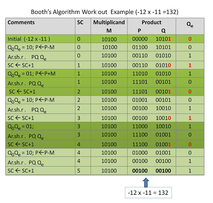
Booth's algorithm uses Arithmetic Shift Right for collecting partial product. Arithmetic Shift right is a sign-extended shift; i.e if the sign bit is 0, then 0 is extended while shifting; if the sign bit is 1, then 1 is extended while shifting. For this reason, n+1 is the register size. You may observe this in our work out in table 9.3. The work out is for (-12x -11). This example is taken to demonstrate the outcome of signed multiplication with Booth's algorithm. Both multiplicand (M) and Multiplier (Q) use 5-bits as against 4-digit binary number.
The partial product and Product is collected in P and Q register. The Q register initially holds the Multiplier; as it gets shifted out with every digit multiplication, the space in Q register is occupied by partial product. Qe is a 1-bit register holding the outgoing bit. Together PQQe is treated as one entity during the arithmetic shift, whereas only P is considered for addition or subtraction of multiplicand. The multiplicand is loaded in M. Both Multiplicand and Multiplier are loaded in the simple binary form if these are positive numbers and in 2's complement form if these are negative numbers. The shift counter stops the operation once it reaches the digit count of Q, in this case, 4. Q0Qe are evaluated at every step to decide the operation to be carried out on M and P.

It is seen that the resulting Product of multiplying two negative numbers is a positive number which is correct. One need not handle the signs separately. It is handled as part of the algorithm. The flow chart and the datapath may be drawn by an interested reader as an exercise or the reader may contact the author.
There is a category of Multipliers called Array multiplier which avoids this sequential operation and produces the result at once. These require a large number of gates for implementation. However, with the advancement in VLSI, it is a reality. Different CPUs have different implementations.

