In a computer, the basic arithmetic operations are Addition and Subtraction. Multiplication and Division can always be managed with successive addition or subtraction respectively. However, hardware algorithms are implemented for Multiplication and Division.
It is to be recollected that computers deal with binary numbers unless special hardware is implemented for dealing with other number systems. Although instructions may be available for treating signed and unsigned operations, the programmer must deal with the numbers and handling of the result. The hardware assists the programmer by way of appropriate instructions and flags.
Addition
Adding two numbers is an addition. We may add signed or unsigned numbers. When we add two numbers, say 8 and 5, the result is 13 i.e. while adding two single-digit numbers, we may get a two-digit number in the result. A similar possibility exists in the binary system too. Thumb rule of binary addition is:
        	0 + 0 = 0
			0 + 1 = 1
			1 + 0 = 1
			1 + 1 = 10
Examples (a –e) of unsigned binary addition are given in figure 8.1.

Adder
The hardware circuit which executes this addition is called Adder. There are two types of adders namely Half adder and Full adder. Basic adder circuit does 1-bit addition and is extended for n-bit addition. The adder circuit characteristics are detailed by a circuit, a truth table, Formula and a block symbol. The adder circuits are constructed from logic gates which satisfy the formula as per truth table. These are also called combinational logic. A Combinational logic output reflects the input without clocking.

The Half Adder (HA) has two inputs (A, B) and two outputs (Sum and Carry). The Sum is XOR of input while the Carry is AND of the input. The Half Adder is detailed in figure 8.2.
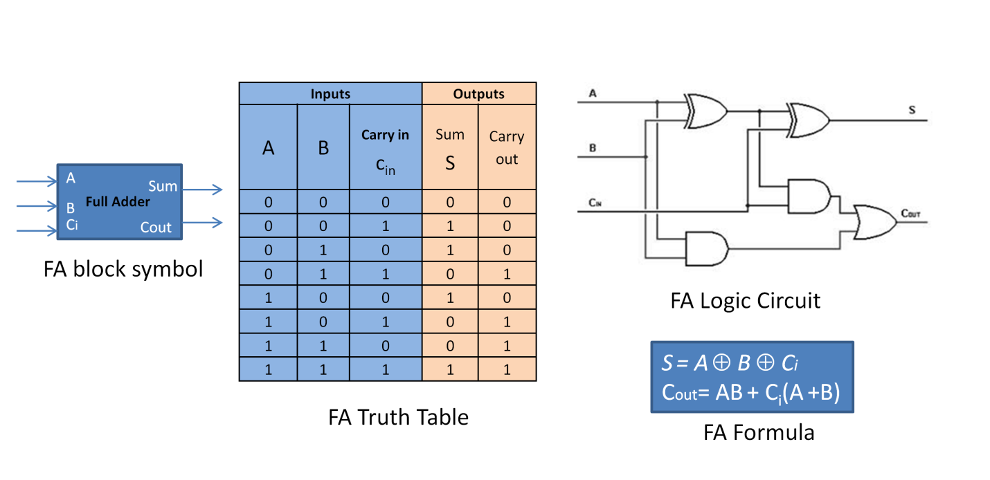
A Full Adder (FA) also performs 1-bit addition but taking 3 inputs (A, B and Ci) and produces two outputs (Sum and Carry). Like HA, FA generates result consisting of Sum (S) and Carry out (Cout). Cout is used as Ci+1 while cascading for multiple bits of a word. Full Adder is detailed in figure 8.3. A full adder can also be constructed using half adder blocks as in figure 8.4.


Subtraction
Subtraction is finding the difference of B from A i.e A-B. Basis of binary subtraction is:
        	0 - 0 = 0
			0 - 1 = -1
			1 - 0 = 1
			1 - 1 = 0
Of course, the usual borrow logic from the adjacent digit is applied as in the case of decimal numbers. Examples of signed binary Subtraction is as below:

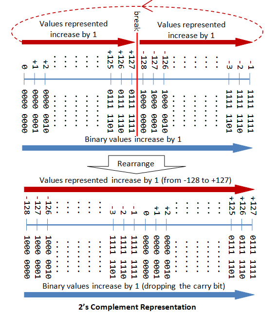
You may note that the above examples are in sign-magnitude representation. In sign-magnitude form, MSB is reserved for sign representation. This is only for basic understanding. Computers internally use 2’s complement representation.
Recall: In 2’s complement representation MSB is sign bit, (n-1) bits of the represent magnitude of the number. Conversion sample for 8-bit word is shown in figure 8.5.

2's Complement for Subtraction
"1's complement + 1 = 2's complement"
Generating this 2's complement is very simple using an XOR circuit. The XOR circuit will generate 1's complement. A control signal called SUBTRACT is used as add value of 1. This way, an adder executes subtraction. See the example below, where case (b), case (c) and case (e) are worked out as 2's complement representation; and A-B becomes A + (2's complement(B)). The result is obtained in 2's complement form discarding the carry. Observe that this method works for all kind of data.

Interpreting 2's complement numbers
- Observe the sign bit (MSB)
- If '0', the number is positive; the (n-1) bits mean the absolute value of the number in binary
- If '1', the number is negative; (n-1) bits mean the 2’s complement value of the number in binary; Invert the (n-1) bits and add 1 to get the absolute value of this negative number.
Error Detection and Status Flags
No one does maths perfectly, but computers can do, provided your data is right! There is a probability that your data may not be rightly defined or may be out of range. For this reason, the CPU detects certain errors like OVERFLOW(O), UNDERFLOW(U) and CARRY(C). It also detects SIGN(S) and ZERO(Z) status. The acronym is ZSOC (Zero, sign, Overflow and Carry) as many processors may treat overflow and underflow together as out of range. The detection is done by the Arithmetic and Logic Unit (ALU) of the CPU. Upon detection corresponding flag is set to ON status. These flags have bit positions allotted in the Processor Status Register and most famously known as Processor Status Word (PSW). ZSOC flags are collectively known as Condition Codes. The purpose of these Condition Codes status flags is to facilitate the programmer to catch data dependant errors and act accordingly.
Overflow: To put in simple English, when a result obtained exceeds the maximum number possible to be represented, Overflow is said to occur. In other words, the addition of two numbers with sign bit ‘0’ resulting in value with sign bit '1' is said to be an OVERFLOW.
For example : An 8 bit word can maximum represent +127 decimal, 01111111 in binary. If we add, 120 + 10 -> 130;
	120	->	0111 1000
	10	->	0000 1010
			---------
            1000 0010 -> in sign magnitude form, MSB (Mos significant bit) '1'
                				means negative number while we expect +130
Max is +127, hence this is an overflow scenario
In Overflow scenario, the result is wrong and this needs to be communicated to the programmer/user that there is an error encountered. This situation is detected by the CPU hardware and sets a status bit called "OVERFLOW". The user, if interested, can catch this error by reading this OVERFLOW status bit and take necessary action over the data handling.
Underflow: While Overflow is related to positive magnitude, Underflow is related to negative magnitude for the same reasons. As an example, when you add two negative numbers like -120 and -10, the result expected is -130 which is beyond the representable range in an 8-bit signed word definition. This is a scenario of UNDERFLOW. In other words, the addition of two numbers with sign bits '1' resulting in a number with sign bit '0' is said to be UNDERFLOW. The CPU hardware detects and sets a status bit called UNDERFLOW to this effect. Again, this status bit is accessible to the programmer/user to take necessary action over the data handling.
Carry: CARRY is another status detected and set by CPU while executing arithmetic instructions. CARRY flag is relevant to Unsigned arithmetic operations while OVERFLOW and UNDERFLOW are relevant to signed operations.
The CARRY Flag is set by the CPU at the end of arithmetic operations if there is a Carry (Cout) out of the most significant bit of the word. The Carry is set at the end of an execution cycle of the addition or subtraction instructions. Many CPUs do not differentiate between signed and unsigned operations, in which case the CARRY and OVERFLOW may both be set by the CPU. However, there are CPUs which have different instruction codes and instructions for signed and unsigned integer operations and in this case, the CPU appropriately sets the CARRY or OVERFLOW flag.
Never forget that it is the programmer who decides whether he is operating with signed or unsigned numbers. So the programmer has to decide whether he should catch OVERFLOW, UNDERFLOW or CARRY flag for error detection and corrective action.
ZERO: At the end of an instruction execution cycle, if the accumulator value is zero, this status bit is set by CPU. This could be a possibility at the end of arithmetic or logical instructions or load instructions.
SIGN: Sign bit reflects the MSB of the accumulator. This is also set at the end of Instruction execution cycle.
n-Bit Adder Formation
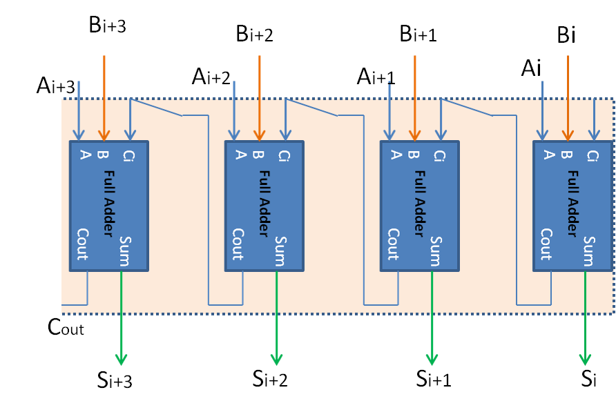
A 4-bitFull Adder is integrated by cascading four numbers of 1-bit adders as in figure 8.6. When cascaded the Cout of ith goes as Cin of i+1th position and hence the carry is said to be propagated. S is the Sum bits, Cout is the final Carry out of the adder. A and B are the input numbers. Ci is carry-in if available. Such cascading can be extended to any number of bits using 1-bit FA or n-bit FA blocks.

This method of Adder expansion is known as Spatial Expansion as the output of all the n-bits are available at the same time as 1-bit operation, probably in one clock cycle. Spatial expansion is also known as Parallel Adder. The other name for this method is Ripple Carry adder as the carry is propagated internally. However, for large n-value, the carry propagation delay for clean and settled output proportionately increases. This is a disadvantage of Ripple Carry Adder which is solved by Carry-Look-Ahead Adder Technique.
Carry Look Ahead Adder
This is also a spatial expansion and ripple carry type. The Carry Look Ahead Adder (CLA) uses specialized logic called Carry Look ahead Logic to compute carries in parallel and hence is faster than Ripple Carry Adder.

CLA Adder generates two other signals namely Propagate Carry and Generate Carry which can be used by the next stage for Carry Calculation.
Propagate Carry Pi = Ai + Bi
i.e when either of the number has '1' in the bit position, the carry is likely depending on the Ci

Generate Carry Gi = AiBi
i.e. when both the numbers have '1' in their bit position in which case carry is sure to be generated.
We already have defined the formula for Sum and Carry as
S = A ⊕ B ⊕ Ci
Cout = AB + Ci(A+B)
The carry formula can be rewritten in terms of Propagate and Generate carry as Cout = Pi + CiGi.
In a Carry look-ahead adder, the carries are computed in parallel using carry look-ahead logic, in one gate delay as compared to 2-gate delays per bit in the case of Ripple carry adder.

