Interrupts are Interruption to CPU. CPU is a busy taskmaster. Any subsystem requiring the attention of the CPU generates Interrupt. INTERRUPT (INT) is both a control and status signal to the CPU. Generally, the memory subsystem does not generate Interrupt. The Interruption alters the CPU execution flow. Recognising and servicing Interrupts is fundamental to any processor design.
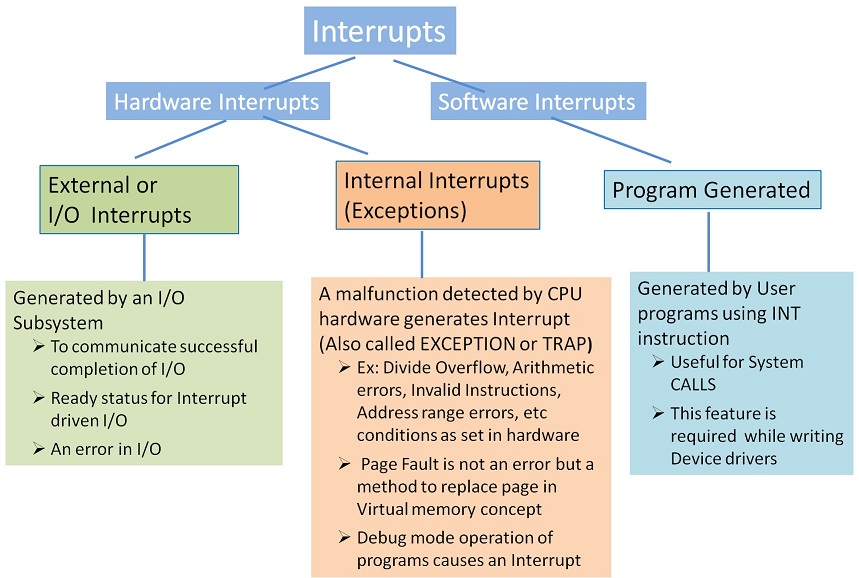
Interrupts are generated by I/O subsystem, CPU or Software. Interrupts categorization and details are detailed in figure 23.1.

An Interrupt handling mechanism has the following characteristics:
- Able to identify that an interrupt is pending
- Identify the type of interrupt
- Identify the source of Interrupt
- Control the interrupt mechanism
- Identify or calculate the ISR address
- Context switching mechanism
Interrupt Service Routine
Most of the Interrupts are asynchronous. When an Interrupt occurs,
- The execution flow control is transferred to the corresponding Interrupt Service Routine (ISR)
- Once the ISR is completed, the original execution flow restarts from the interrupted point as shown in figure 23.2. ISR is also called Interrupt Handler.
- Interrupts are recognized and serviced by CPU at the end of the current instruction execution.
- Context switching of the Processor happens while breaking for ISR. This part is common to all kinds of interrupts.
- What happens in the ISR routine is specific to the Interrupt. For example, if divide overflow error, the ISR block may send a msg to the user informing the error and terminate the program. If page fault, page swapping happens. If I/O interrupt, status reading first happens; based on the status further course is taken up.

In the case of I/O interrupt, the cause is analysed in the ISR. Any remedial action to be taken is also part of the ISR. For example, if an interrupt is caused for informing an error in the device, the same needs to be informed to the user and any possible retry to be done for recovery from the error.
Context switching
Essentially, an Interrupt alters the flow of the program execution. Context switching is about the CPU taking necessary steps to store the current status of the CPU so that on return the CPU status is restored for resumption. Context switching helps the CPU to switch processes or tasks and is an essential feature supported by the Operating System.

Identifying the ISR Location
By now you would have guessed the increasing complexity of information regarding Interrupt handling especially the puzzle about the CPU getting ISR location address. The ISR location depends on the source of Interrupt. The interrupting device or process provides the CPU with this information about ISR. This information is provided in the form of type code, or a vector, or an address where the vector can be found. Generally, the type codes are translated into a vector by the processor. Interrupt vectors are either the address of the ISR or pointer in a vector table where the relevant ISR address is found. Although the vector table composition is implementation-specific, an example of a vector table is shown below.
| Interrupt Vector | ISR Address |
|---|---|
| 1 (Page Fault) | 1234 |
| 2 (Divide Overflow) | 1658 |
| 3 (IO Interrupt) | 2340 |
| * | * |
| * | * |
| * | * |
| n (Floating Point Error) | 5240 |
Interrupt Identification
To put simply, as shown in figure 23.3 the I/O Interrupt is conveyed to CPU by asserting the signal INTR. When the CPU recognizes the INTR, it returns the signal INTR ACK as an acknowledgement. From figure 23.3, you may understand that the line INTR is a summation of interrupts from all the I/O controllers. The issue is how is the interrupting device identified. The possibilities for a pending interrupt are
- Only one of the I/O controller has raised the Interrupt
- More than one I/O controller has raised the Interrupt
The hardware is designed to handle the second case of as many I/O controllers may raise interrupts asynchronously but conveyed to CPU on a single line.

The Points to be noted in identifying the interrupting device are:
- The CPU services all the interrupts one by one as it finds the chance to service the interrupt.
- Amongst the I/O controllers, Interrupt priority is assigned in the hardware. So the highest priority one gets serviced first and cleared of pending interrupt. This method is called Daisy Chaining. Generally, the slow speed device controllers are assigned lower interrupt priority. Starvation may be a possibility. The INTR and INT ACK signals are passed through all the controllers in the order of the pre-assigned priority
- Yet the question of which device is not answered. The identification is done by one of the following methods
- Polling - As part of the ISR by reading the various status registers, the interrupting device is identified. In this case, the I/O ISR always starts from a particular common vector address. Polling is a Software method.
- Vectored Interrupts – Extra signal lines between CPU and I/O are run to indicate the INT CODE (type code) of the interrupt. Every controller is assigned an INT CODE. For example, if there are eight I/O controllers, 3 lines are used so that the INT CODE is presented in binary coded form. This type code, as said earlier is useful in generating the vector for ISR.
- Multiple Interrupts Handling – Two possibilities exist:
- Simultaneously more than one interrupt could be pending necessitating some priority assignment and identification mechanism. We have just discussed this case.
- During an ISR, another interrupt could come in. A decision to deal with (as Nested Interrupt) or to defer (Masking the Interrupts) is required. Not all interrupts are maskable.
Internal interrupts have higher priority over I/O interrupts. Internal interrupts are vectored interrupts. In the case of software interrupts too, the instruction code will help identify the ISR vector.

